E-mail: [email protected] Whatsapp: +8613647327093 Tel: +86-731-8403-0163
E-mail: [email protected] Whatsapp: +8613647327093 Tel: +86-731-8403-0163
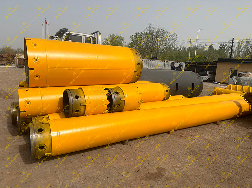
Segmented casing plays a vital role in pile foundation construction. It is a key technical measure used to ensure pile quality and construction safety under complex geological conditions. Once problems occur with the casing, they can easily lead to serious defects such as hole collapse, mud inclusion in the pile body, or pile breakage, directly weakening the bearing capacity and structural safety of the foundation. This article introduces the common problems of segmented casing in pile construction and their solutions, aiming to help you complete each project more smoothly.
1. Local deformation (dent, bending):
Usually occurs at the lower edge or middle of the casing. When encountering underground boulders, hard obstacles, or accidental collisions with drilling or lifting equipment, localized stress concentration leads to deformation.
2. Overall out-of-round (elliptical deformation):
In ultra-deep holes or extremely soft soil, uneven soil pressure distribution around the casing or large uneven friction during extraction may compress the cross-section into an elliptical shape.
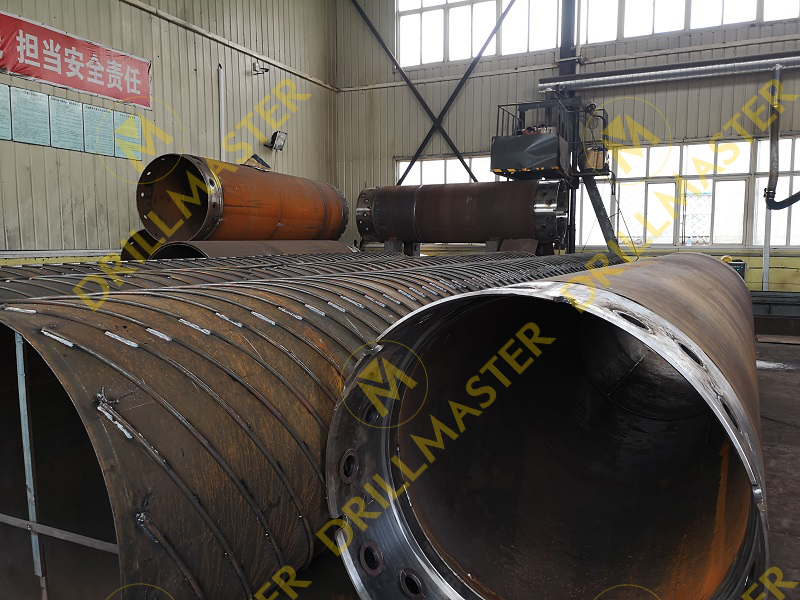
3. Weld cracking:
If welds at the casing joints have quality defects (such as pores or slag inclusions), repeated vibration and loading can cause cracks to propagate, eventually leading to casing rupture.
4. Material fatigue and corrosion:
After long-term reuse, steel strength decreases due to fatigue. Meanwhile, corrosive media in groundwater or soil (e.g., chloride ions, sulfates) accelerate corrosion, especially in the heat-affected zone of welds, causing wall thickness reduction or even perforation.
Solutions:
1. Strict inspection before use:
Check material reports, wall thickness tolerance, and roundness before delivery. Perform visual inspection and ultrasonic thickness measurement; conduct non-destructive testing on suspicious areas.
2. Use high-strength steel:
For complex geology and deep holes, choose high-strength, high-toughness alloy steel casings and increase wall thickness at critical sections (e.g., the first lower section).

3. Add reinforcement structures:
Weld stiffeners on deformation-prone areas (such as the ends) or adopt double-walled casing design to enhance resistance to deformation.
4. Standardized operation and protection:
Use geological reports to predict obstacles before sinking the casing and pre-drill with a small bit if necessary. Use protective padding during lifting and storage to avoid collisions. In corrosive soil, apply anti-corrosion coatings or sacrificial anode protection.
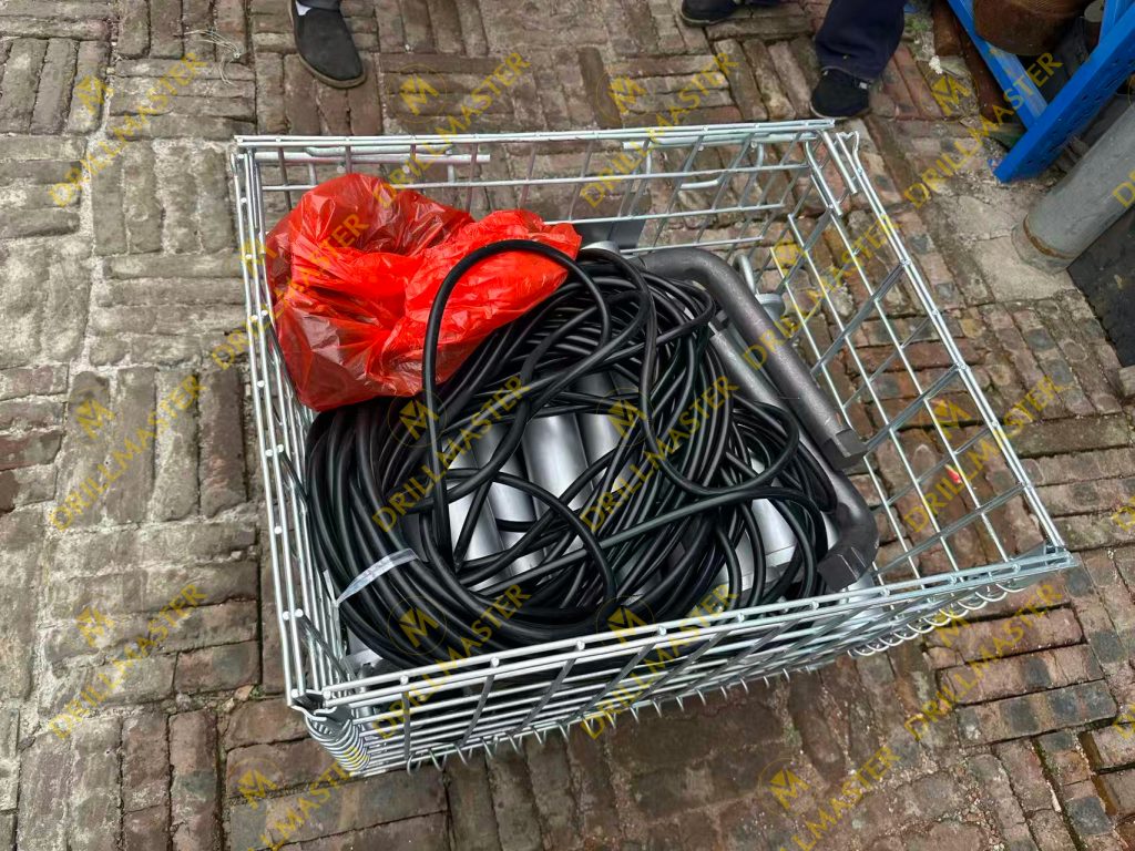
1. O-ring or gasket damage:
Seals at joints may be crushed or twisted during installation, or lose elasticity due to aging or corrosion.
2. Deformation of sealing groove:
The sealing groove at the joint may deform due to impact or overload, making it unable to compress the seal effectively.
Consequences:
Mud leaks from the joint gaps. External soil and sand may flow into the casing, causing concrete contamination. Meanwhile, the slurry level inside the casing drops, potentially leading to hole collapse.
Solutions:
1. Replace seals every connection:
Making “replace O-rings or gaskets with new ones after every disassembly” a mandatory rule. Even if the old seal looks intact, its elasticity may be insufficient for new pressure.
2. Inspect and repair sealing groove:
Include sealing groove inspection in routine procedures. Use magnifiers and gauges to check for dents, burrs, or deformation.
Minor damage can be carefully repaired using a fine file or oilstone; severely deformed joints must be repaired or scrapped.
3. Adopt multi-seal design:
Prefer joints with primary and secondary seals (e.g., double O-rings). Even if one seal fails, the backup provides reliability.
1. Difficulty sinking (“cannot push down”):
Mainly caused by end resistance and side friction. When the casing bottom meets hard rock or dense gravel, end resistance is high. In clay soil, side friction increases over time (thixotropy).
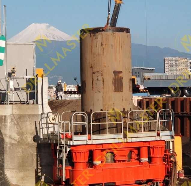
2. Difficulty extracting (“cannot pull out” or “locked”):
This is the most critical risk. Major causes include:
1)Vacuum suction effect:
Rapid extraction forms negative pressure between the casing bottom and concrete surface.
2)Concrete bonding and lateral pressure:
Concrete shrinks during setting but exerts high lateral pressure, tightly wrapping the casing. If extraction is delayed, increasing strength causes bonding force to surge.
3)Soil rebound and compression:
During sinking, displaced soil rebounds and clamps the casing tightly.
Solutions:
1. For sinking difficulty:
1)Assist with rock breaking/excavation:
Use a rotary drill or grab hammer inside the casing to remove obstacles or hard rock first.
2)Pre-drill or high-pressure water jetting
Drill a pilot hole with smaller diameter at the casing position or install high-pressure water pipes outside the casing bottom to reduce end and side resistance.
2. For extraction difficulty (systematic measures):
1)Optimal timing:
Start extraction when concrete has some plastic strength (before initial set) but bonding force is still low. Use “dynamic extraction”—slightly rotate or lift the casing every 10–20 minutes after pouring to break adhesion.
2)Apply anti-friction agents:
Coat the casing exterior (especially lower section) with high-efficiency lubricants (e.g., polymer slurry, bentonite slurry) to form a durable lubrication film.
3)Ensure adequate equipment capacity:
Extraction equipment (crane, hydraulic jacking frame) must have sufficient reserve capacity (typically 1.5–2 times the estimated friction).
Technical measures:
1)Twist-and-lift extraction:
Use full-rotation equipment to apply upward force while slowly rotating clockwise and counterclockwise to break static friction.
2)Synchronous grouting:
During extraction, inject slurry into the gap between casing and soil through pre-installed side pipes to fill voids and reduce negative pressure and friction.
1. Poor slurry management:
Slurry with low density provides poor wall support, leading to collapse; insufficient viscosity or gel strength results in poor cuttings transport and excessive sediment.
2. Insufficient hole cleaning:
Excessive sediment at the hole bottom reduces end bearing capacity. During casing extraction, sediment may fall into the gap, increasing friction or even jamming the casing.
3. Uncontrolled concrete pouring:
Interruption causes pile breaks; excessive tremie pipe embedment increases concrete uplift resistance and lateral pressure on the casing; excessively fast pouring also sharply increases lateral pressure.
Solutions:
1. Slurry parameterization:
Determine slurry mix design and performance indices (density, viscosity, sand content, pH) in advance based on geology, and assign personnel for regular testing and adjustment.
2. Secondary hole cleaning:
After lowering the reinforcement cage and before pouring concrete, perform secondary cleaning to ensure sediment thickness meets specifications.
3. Accurate control of concrete pouring:
1)Calculation and monitoring:
Calculate the volume of the first batch of concrete in advance to ensure adequate tremie embedment. Measure embedment depth throughout pouring; the tremie must never be lifted above the concrete surface.
2)Maintain continuity and stability:
Ensure continuous concrete supply and schedule truck mixers reasonably. Control pouring speed to avoid being too fast or too slow.
4. Strengthen personnel training and technical briefing:
Ensure all operators, especially drill rig operators and foremen, thoroughly understand the principles and consequences behind each step, and develop their ability to anticipate and handle problems.
Contact Us


