E-mail: [email protected] Whatsapp: +8613647327093 Tel: +86-731-8403-0163
E-mail: [email protected] Whatsapp: +8613647327093 Tel: +86-731-8403-0163
What is a slewing bearing? Slewing bearings are called the "joints of machines". They are important transmission components necessary for machinery where two parts need to perform relative rotary motion while simultaneously bearing axial forces, radial forces, and overturning moments.
1. Connect the vehicle body and chassis through bolts.
2. Together with the slewing reducer, enable the upper carriage to achieve 360°rotation, transmitting the power and force from the engine and working parts.
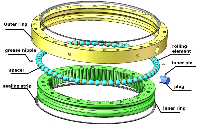
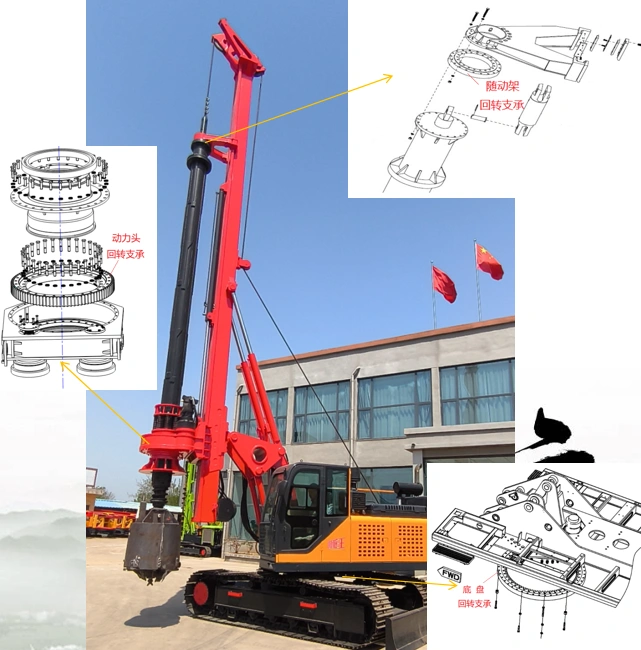
What slewing bearings are used in a rotary drilling rig? What are the respective structural types?
1. Follower frame: single-row ball, non-geared type
2. Power head: single-row ball external‑tooth type, double‑row ball external‑tooth type, single‑row ball non‑geared type, double‑row ball non‑geared type
3. Undercarriage: single-row ball internal‑tooth type, cross roller internal‑tooth type, three‑row roller internal‑tooth type.
1. Before installing the slewing bearing:
First, confirm that the slewing bearing model is correct and verify that the gear tooth profile angle matches. Also inspect the mounting surface of the host turntable – it must be flat, free of debris, burrs, etc. The mounting surface shall achieve the flatness specified in the table below. If the requirement cannot be met, perform grinding or use engineering surface sealant when installing the slewing bearing to prevent deformation of the bearing after bolt tightening.
2. Soft zone of the bearing rings:
The slewing bearing rings have quenched soft zones. For the gear ring, the soft zone is marked with an "S" on the non‑machined surface; for the outer ring, the soft zone is located at the plug hole. During installation, position the soft zone in a non‑load or light‑load region. Then identify the point of maximum gear runout (marked with green paint).
3. Installation:
Use a crane to lift the upper structure of the excavator, and install the slewing bearing onto the base. Position the soft zones of the inner and outer rings 90° away from the main load zone. Also, check the fit between the slewing bearing and the mounting surface (usually using a feeler gauge). Then align the upper swing platform mounting holes with the outer ring mounting holes of the slewing bearing; after alignment, use a round bar with a diameter close to that of the bolts to pin the position, then install the bolts. Check the slewing bearing rotation. After the slewing bearing is installed, do not perform welding on the base.
4. Tightening the bolts:
Installed bolts must have sufficient preload – the preload should be 0.6–0.7 times the bolt yield strength.
Notes:
a. Do not use full‑thread bolts.
b. Reusing old bolts, nuts, and washers is not recommended.
c. Do not use split washers (e.g., spring washers).
d. After the slewing bearing is installed and put into operation, after 100 consecutive working hours, the preload torque of all mounting bolts shall be thoroughly checked. Thereafter, repeat the above check every 500 operating hours.
5. Gear backlash adjustment:
To ensure smooth rotation of the slewing bearing, perform gear meshing inspection before tightening the mounting bolts. The backlash is typically measured with a feeler gauge at the point of maximum radial gear runout, and the minimum backlash shall meet the values given in the table above.
If the backlash is not within the specified range, adjust the center distance by moving the gear. After adjustment, rotate the slewing bearing at least one full turn to confirm that the minimum clearance at the highest runout point satisfies the requirement. After the slewing bearing is finally secured, check the backlash once more.
1. Avoid “Fatal” Misconceptions
Common maintenance mistakes made by end‑user excavator customers can damage the machine even more than “no maintenance at all”.
Misconception 1: The more grease, the better.
Correct practice: Stop when grease just barely seeps out. The excess grease will lubricate the seal automatically without damaging it.
Misconception 2: Guessing maintenance intervals – “do it when I remember”.
Correct practice: Set intervals according to working condition grades, not by feeling.
Misconception 3: Only greasing, never checking seals.
Correct steps: First wipe the grease nipple clean, then inspect the seals for cracks or oil leaks. Replace immediately if problems are found; otherwise the maintenance is wasted.
2. Standard Maintenance Procedure
A. Preparation phase: tools + safety
Tool list:
#2 lithium grease (use a well‑known domestic or international brand; cheap generic grease lacks viscosity and runs off easily)
High‑pressure grease gun
Rags (for cleaning nipples)
Safe operation:
Move the excavator to an open, unoccupied area. Lower the working attachment completely (bucket on the ground, boom naturally down). Turn off the engine. Engage the safety lock lever – this step is never optional.
B. Inspection phase: inspect before greasing
Use a rag to wipe the grease nipple(s) on the slewing bearing (the nipple is normally on the outer cylindrical surface of the outer ring; if it is not a centralized grease line, the port is usually a countersunk hole).
Check whether the nipple is clogged and whether the sealing strip has cracks.
If the nipple is clogged, do not force it! Remove the nipple, gently clear it with a thin wire, then give one pump of the grease gun to expel contaminants.
C. Greasing phase: cross‑greasing + slight seepage
Grease the first nipple until grease just barely seeps out at the lap joint of the lower seal. Stop for 30 seconds to allow the grease to penetrate into the raceway. Move to the next nipple and repeat the operation, ensuring the raceway receives grease.
D. Multi‑angle supplementary greasing: even distribution
Start the excavator. Lift the bucket 30 cm off the ground (not too high, to avoid swaying the upper structure). Slowly swing the upper structure to 45°, then lower the bucket to the ground and turn off the machine.
Follow the sequence 0° → 45° → 90° → 135°, adding a small amount of grease at each angle (again, stop when slight seepage appears). After finishing, start the machine and slowly swing the upper structure two full circles to distribute the grease evenly inside the raceway.
E. Final check: look for abnormalities
After two full circles, stop and check the seals for oil leakage (a slight seepage is normal; heavy leakage requires seal inspection). Feel the outer ring of the slewing bearing with your hand – pay attention to any obvious abnormal noise or rough movement.
3. Condition‑Based Maintenance Table: Different treatments for different working conditions
A. Normal conditions (municipal road repair, earthmoving, rural construction)
Every 500 hours, or once a month.
B. Heavy‑load conditions (quarrying, large‑scale infrastructure)
Every 300 hours; inspect seals after each work shift.
C. Wet / saline‑alkali conditions (rainy regions, seaside work, pond/fish farm desilting)
Every 200 hours; perform maintenance immediately after wading or working in sludge (mandatory if water level exceeds the centreline of the carrier roller).
D. Long‑term parking (more than 1 month of no use)
Perform maintenance before parking. Every 15 days, start the engine and swing the upper structure two full circles to prevent the grease from solidifying.
E. High / low temperature conditions
- #2 extreme‑pressure lithium grease: -20 °C to +120 °C
- High‑temperature grease: -40 °C to +200 °C
- #2 low‑temperature grease: -60 °C to +120 °C
F. Slewing bearing maintenance for rotary drilling rigs
- Drill pipe slewing bearing: Every 200 hours, or once a month.
- Power head slewing bearing: First check at 50 hours (grease condition); thereafter every 1000 hours or every six months.- Undercarriage slewing bearing: Every 1000 hours or every six months.
Contact Us