E-mail: [email protected] Whatsapp: +8613647327093 Tel: +86-731-8403-0163
E-mail: [email protected] Whatsapp: +8613647327093 Tel: +86-731-8403-0163
In pile foundation construction, completing the drilling does not mean the risks are over. What truly determines a pile’s bearing capacity, structural integrity, and long-term safety often lies in the internal details of the borehole that cannot be seen with the naked eye—whether the diameter meets the design requirement, whether the borehole is vertical, and whether the bottom is properly cleaned. Once deviations occur in these aspects, even if the concrete strength is qualified and the construction process “appears problem-free,” inherent quality risks may still exist in the finished pile.
From a load-transfer perspective, abnormal borehole diameter or local overbreak changes the conditions under which shaft friction is mobilized, leading to uneven stress distribution. Borehole deviation not only increases the difficulty of lowering the reinforcement cage but may also cause eccentric loading of the pile. Excessive sediment at the borehole bottom directly weakens the bearing capacity of end-bearing piles and becomes a trigger for long-term settlement or quality incidents. Once these problems are sealed by concrete, remediation is nearly impossible; they are often discovered only during testing or service, at an extremely high cost.
However, in actual construction practice, the assessment of borehole quality still relies heavily on traditional inspection methods. Tools such as steel tapes or sounding lines can at best measure borehole depth, but they cannot reflect diameter variations, irregular borehole walls, or verticality deviations. Judgments based on operators’ experience—such as “whether it feels smooth” or “whether there is resistance when lifting the drill”—are essentially qualitative. They are difficult to quantify, leave no traceable record, and cannot provide reliable evidence for quality acceptance or responsibility attribution.
This leads to an unavoidable core question: under the premise of not sending personnel down the hole, not damaging the borehole, and not disrupting the construction rhythm, how can truly accurate, comprehensive, and quantifiable borehole data be obtained?
It is precisely against this background that ultrasonic borehole inspection technology has gradually evolved from an “auxiliary tool” into an indispensable means of quality control in modern pile foundation construction.

To understand how an ultrasonic borehole inspection instrument can “see” inside a borehole, it is essential to recognize a basic condition: after drilling, the borehole is usually filled with slurry or clean water, and ultrasonic waves are particularly well suited for stable propagation in liquids. Compared with optical or camera-based methods, which are easily affected by turbidity, ultrasonic waves can maintain good directionality and penetration even in slurry environments, providing natural conditions for nondestructive borehole inspection.
1. Propagation Characteristics of Ultrasonic Waves in Liquids
Ultrasonic waves are essentially high-frequency mechanical waves that propagate at a stable speed and along controllable paths in liquids. When the wave encounters a material boundary—such as the interface between slurry and the borehole wall (soil or concrete)—a distinct reflection signal is generated. The more intact the borehole wall and the clearer the interface, the more stable the reflected signal. Conversely, in cases of overbreak, collapse, or irregular borehole geometry, both the reflection distance and signal intensity change accordingly. This is the physical basis that enables ultrasonic borehole inspection to identify internal geometric characteristics.
2. The “Transmit–Reflect–Receive” Measurement Logic
The working process of an ultrasonic borehole inspection instrument can be simplified into three consecutive steps:
Transmission: The probe emits ultrasonic pulses toward the borehole wall.
Reflection: The sound waves are reflected upon reaching the borehole wall.
Reception: The probe receives the reflected echo signals.
By precisely recording the time interval between transmission and reception and combining it with the known propagation velocity of ultrasonic waves in slurry, the instrument calculates the distance between the probe and the borehole wall. Shorter times indicate smaller diameters, while longer times suggest overbreak or irregular voids.
3. Rotational Scanning vs. Axial Lifting Scanning
To obtain complete and reliable borehole information, ultrasonic inspection does not measure in only one direction:
Rotational scanning: At a fixed depth, the probe rotates 360°, scanning the borehole wall point by point to obtain a complete diameter profile at that depth.
Axial lifting scanning: While rotating, the probe is lifted upward at a constant speed along the borehole depth, forming continuous longitudinal data.
The combination of these two scanning modes effectively performs a three-dimensional scan inside the borehole—from points to surfaces, and from surfaces to volumes—laying the data foundation for diameter and verticality analysis.
4. From “Echo Time” to “Geometric Dimensions”
In the backend system, each echo signal is converted into a specific distance value and matched with the corresponding probe depth and angular position. After algorithmic processing, scattered time data are reconstructed into:
Actual borehole diameter at specific depths
Spatial variation of the borehole axis
Distribution of the borehole bottom interface
What is ultimately presented to construction and management personnel is no longer abstract acoustic signals, but readable, comparable, and traceable geometric dimensions and graphical results. This transformation from “physical signals” to “engineering data” is what gives ultrasonic borehole inspection real on-site decision-making value.
In borehole quality control, whether the diameter truly meets design requirements is often more easily overlooked than whether the depth is sufficient. Many quality issues are not due to an overall insufficient diameter, but rather to local overbreak, underbreak, or highly irregular borehole walls. Once filled with concrete, these hidden problems become permanently embedded in the pile, directly affecting shaft friction and stress uniformity.
1. Single-Point Measurement vs. Full-Circumference Scanning
Traditional inspection methods are typically single-point or limited-point measurements. Using sounding lines or hammers, they provide feedback only from one direction or contact point. Even if the tool can be lowered and lifted smoothly, it is impossible to determine whether significant expansion or deformation exists in another direction.
In contrast, ultrasonic borehole inspection adopts a full-circumference scanning approach. At the same depth, the probe rotates 360° and continuously measures distances to the borehole wall. The result is not a single “point,” but a complete circular data cross-section in which any local abnormality is clearly revealed.
2. How Ultrasonic Technology Builds a 360° Borehole Wall Profile
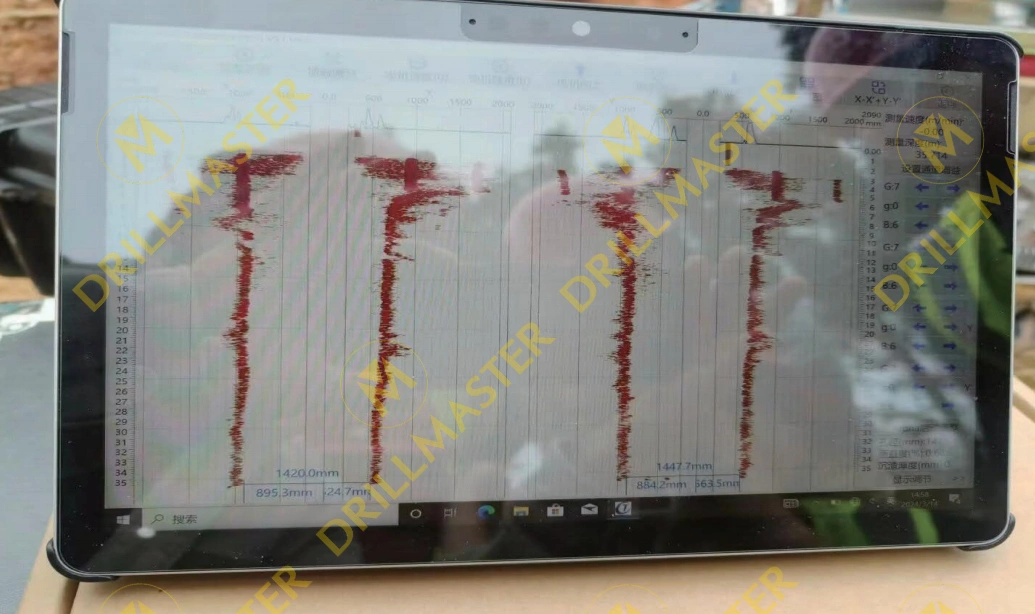
During rotational scanning, each incremental angular rotation triggers one ultrasonic transmission and reception. The system converts:
Echo time → distance to the borehole wall
Probe angle → wall orientation
By correlating these two parameters, a complete borehole wall cross-section at that depth is reconstructed. As the probe is continuously lifted along the borehole, multiple cross-sections are stacked to form a longitudinal profile of diameter variation. Borehole geometry thus becomes a verifiable shape rather than a matter of guesswork.
3. Quantifiable Diameter Indicators: From “Seems Larger” to “Data Speaks”
Based on complete scanning data, the instrument can output multiple quantifiable indicators, including but not limited to:
1) Comparison between actual and design diameter at each depth
2) Local overbreak ratio, indicating how much the diameter exceeds design values
3) Local underbreak ratio caused by collapse backfill or wall contraction
These indicators support not only construction process control but also quality acceptance, inspection reporting, and responsibility determination.
4. Typical Application Scenarios: Problems Often Occur Where Least Expected
In practice, borehole diameter anomalies are strongly related to geological conditions:
Overbreak in soft strata: Such as silty soil or soft clay, where borehole walls are unstable and prone to overbreak during drilling pauses or tool withdrawal.
Irregular shapes in cobble layers or karst formations: Borehole walls may exhibit jagged profiles or local cavities that are nearly impossible to detect with point-based methods but are clearly revealed by full-circumference scanning.
Ultrasonic diameter detection allows contractors to identify risk zones in advance and adjust drilling parameters, wall protection measures, or cleaning schemes before pile formation—controlling problems before concreting rather than attempting costly post-facto remedies.
In pile foundation construction, borehole diameter determines whether a pile is usable, while verticality determines how well it performs. Many projects fail not because the diameter is insufficient, but because the borehole gradually deviates without being noticed, only to cause problems during cage installation, concreting, or long-term loading.
1. Direct Consequences of Loss of Verticality
Significant borehole deviation often leads to a chain of issues:
1) Difficulty in lowering reinforcement cages, including jamming or forced cutting and adjustment
2) Uneven concrete cover thickness, creating durability risks
3) Eccentric pile loading, preventing uniform mobilization of shaft friction and end bearing, and increasing the likelihood of differential settlement
These risks are often difficult to detect before concreting, and once the pile is formed, correction costs are extremely high.
2. How the Instrument Records the Borehole’s Spatial Trajectory
During inspection, the ultrasonic borehole instrument not only measures wall distances but also records the spatial position of the probe at each depth. During axial lifting scans:
Each depth corresponds to a specific spatial coordinate
Attitude sensors and displacement data continuously track deviations from the theoretical vertical axis
As the probe moves upward (or downward), these discrete spatial points are recorded and connected, forming the true borehole axis trajectory. Whether the borehole is vertical, where deviation begins, and in which direction it occurs can all be clearly identified.
3. Data Output: Making Deviation Visual and Quantifiable
Based on spatial data, the instrument typically outputs intuitive results such as:
1) Borehole axis offset curves showing deviation trends with depth
2) Maximum deviation values from the design axis
3) Deviation angles for direct comparison with code requirements
These outputs support both rapid on-site judgment and formal quality documentation for acceptance and review.
4. Fundamental Difference from Traditional “Experience-Based” Judgments
Without quantitative tools, verticality assessment has long relied on experience:
“It feels a bit off when lifting the drill.”
“The reinforcement cage doesn’t go down smoothly.”
Such judgments reflect outcomes rather than process control. Ultrasonic inspection changes this by providing:
Clear knowledge of how much deviation exists and where it starts
The ability to correct issues during drilling rather than discovering them afterward
This shift from subjective experience to objective data makes verticality a truly manageable and traceable construction parameter.
Among borehole quality issues, bottom sediment is often the most concealed yet the most critical. Diameter and verticality problems may become apparent during cage installation, but insufficient bottom cleaning can easily be overlooked when everything appears normal—only to reveal consequences during load testing or service.
1. Mechanism of Sediment Impact on End-Bearing Capacity
For end-bearing piles or piles with significant end-bearing contribution, direct and reliable contact between concrete and the bearing stratum is essential. Excessive sediment at the borehole bottom acts like a “soft cushion” between the pile tip and the bearing layer:
Sediment is compacted during concreting but lacks sufficient strength
End-bearing force cannot be effectively transferred
Under load, the sediment layer compresses or shears first, causing excessive settlement
Such issues are nearly impossible to remedy after construction and can compromise long-term structural safety.
2. How the Instrument Detects Sediment Thickness
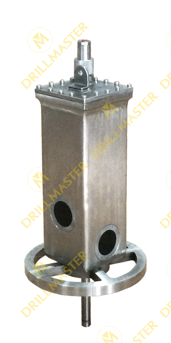
Sediment thickness detection is based on recognizing differences in contact response between the probe tip and borehole media. The mechanism can be summarized as “contact → force response → signal change → thickness determination”:
1) Probe lowering: Establishing a reference position as the probe approaches the borehole bottom under self-weight or preload
2) Soft contact identification: When the probe first contacts loose sediment, compressible and low-stiffness behavior produces gradual changes in displacement or force signals
3) Hard contact identification: When the probe reaches the bearing stratum, stiffness increases sharply, causing a clear inflection or sudden change in signals, identified as the true borehole bottom
Rather than acting as a direct measuring rod, the probe infers sediment thickness by sensing mechanical response differences between soft and hard media—well suited for underwater and slurry conditions without damaging the borehole bottom.
3. Sediment Thickness Calculation Logic
The system compares the depth at first contact with sediment to the depth at contact with the bearing layer. The difference between these two depths is the sediment thickness. This process is automatically calculated in real time, minimizing subjective judgment.
4. Key Construction Decision: Is It Safe to Lower the Cage?
The ultimate purpose of sediment detection is to support on-site decisions:
1) Whether measured sediment thickness meets code or design limits
2) Whether secondary cleaning or slurry optimization is required
With ultrasonic sediment detection, borehole bottom cleanliness is determined by data rather than experience. Although it adds a detection step, it is often critical for preventing quality incidents and ensuring long-term pile performance.
Any inspection method has value only when its results directly guide construction actions. The significance of ultrasonic borehole inspection lies not merely in identifying problems, but in transforming complex internal data into decision-making tools that site personnel can understand and use.
1. Common Data Output Formats
Results are typically presented in multiple forms:
Numerical tables: Actual diameter, deviation, and sediment thickness at each depth, suitable for technical review and compliance checks
Profiles and 3D borehole models: Visual representation of diameter changes, axis deviation, and bottom conditions, easily understood even by non-technical staff
This combination ensures that data are both rigorous and intuitive.
2. Approval to Lower Reinforcement Cages
Before cage installation, inspection data provide clear go/no-go criteria regarding diameter sufficiency, verticality compliance, and sediment thickness, preventing problematic progression to the next stage.
3. Adjustment of Drilling Parameters
Depth-dependent diameter and verticality data enable targeted optimization of drilling pressure, rotation speed, tool configuration, or advance rate.
4. Optimization of Borehole Cleaning Processes
Sediment data directly reflect cleaning effectiveness and support decisions on secondary cleaning, circulation methods, or slurry adjustments, with follow-up inspections verifying improvements.
5. From “Inspection Report” to “Construction Tool”
When inspection data directly determine cage installation, drilling strategy, and cleaning requirements, ultrasonic borehole inspection becomes an integral construction management tool—marking the shift from result-based inspection to process-based quality control.
Although multiple methods exist for borehole quality checks, few perform reliably under complex geology, turbid slurry, and fast-paced construction. Comparisons highlight the advantages of ultrasonic inspection.
1. Compared with Manual Measurement
Manual methods are simple and low-cost but limited to depth measurement, rely heavily on experience, and lack traceable records. Ultrasonic inspection provides multidimensional, continuous, and quantifiable data.
2. Compared with Camera-Based Inspection
Camera inspection offers visual intuition but requires clear water and struggles in slurry environments, providing limited quantitative geometry. Ultrasonic inspection, independent of optical clarity, works reliably in turbid slurry and delivers precise geometric data.
3. Core Advantages of Ultrasonic Borehole Inspection
Unaffected by turbidity or slurry
Quantifiable, traceable results
High efficiency and repeatability
These features have transformed ultrasonic borehole inspection from a supplementary method into a key tool for proactive risk control and quality assurance in pile construction.
The role of borehole inspection is evolving. The focus has shifted from merely judging whether results are acceptable to ensuring that processes are controllable.
Trends in Borehole Inspection
As project scale and quality requirements increase, inspection is moving from result acceptance to process control and data management—an evolution in which ultrasonic borehole inspection plays a central role.
Positioning in Modern Pile Construction
Ultrasonic borehole inspection is not a tool to “find fault,” but one that helps identify risks early, supports data-driven decisions, and keeps quality under control before pile formation.
True quality management is not about fixing problems after they appear, but about seeing what the naked eye cannot see—before concrete is poured. This is why ultrasonic borehole inspection has gradually evolved from an “optional” choice into a “must-have” for high-standard pile foundation construction.
Contact Us