E-mail: [email protected] Whatsapp: +8613647327093 Tel: +86-731-8403-0163
E-mail: [email protected] Whatsapp: +8613647327093 Tel: +86-731-8403-0163
Auger drilling tools are responsible not only for cutting through soil or rock, but also for loading, conveying, and discharging drilling spoil. Different auger configurations fundamentally affect whether the excavated material can be continuously and efficiently transported from the bottom of the borehole to the surface.Based on structural design, augers are primarily classified into six categories:
1)Straight-shaft single-start single-flight (soil)
2)Straight-shaft double-start single-flight (soil)
3)Straight-shaft double-start double-flight (soil)
4)Rock single-cone single-flight
5)Rock double-cone single-flight
6)Rock double-cone double-flight

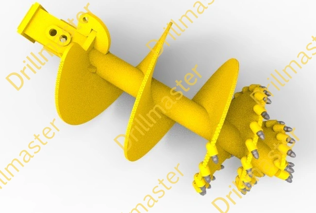
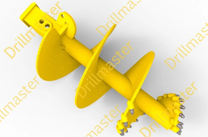
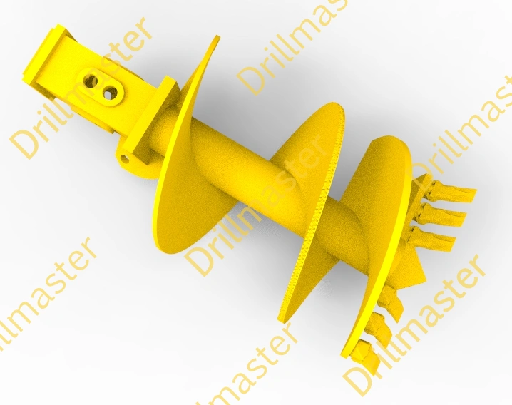
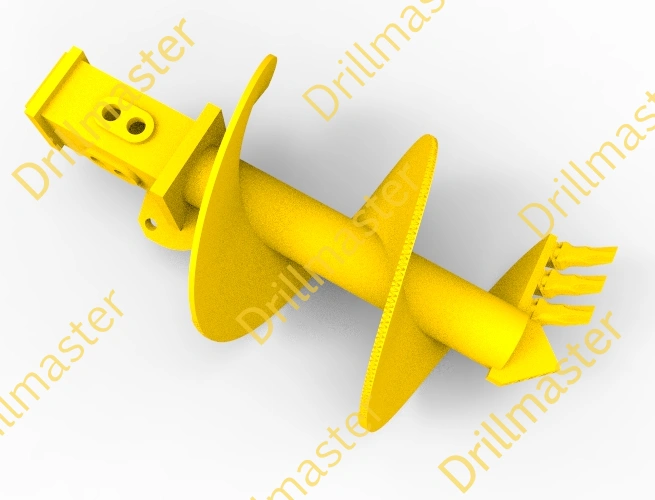
In rotary drilling and piling construction, an auger does more than cut through soil or rock. Once the cutting teeth break the ground into soil, clay, gravel, or rock fragments, the auger flights must capture and transport the loosened material from the bottom of the borehole toward the surface.
This makes the auger flight an important part of the spoil removal process. The flight geometry determines how much material can enter the auger, how efficiently it can be carried upward, and how much spoil remains on the tool during lifting.
How Auger Flights Convey Drilling Spoil
As the auger rotates, its cutting teeth break the ground at the bottom of the borehole. The loosened material enters the spaces between the flights and is then carried upward as the auger continues to rotate.
In this process, the auger flight works much like a continuous conveyor. The rotating flight creates a helical conveying path that moves drilling spoil away from the cutting area and toward the top of the borehole.
The efficiency of this process depends on several factors, including the flight diameter, pitch, number of starts, and the characteristics of the drilled material.
How Flight Pitch Affects Spoil Carrying
The spacing between adjacent flights determines the available space for drilling spoil.
A relatively large flight pitch provides more room for soil, gravel, or larger fragments to enter the conveying space. This can be beneficial when drilling through materials containing larger particles.
However, a larger pitch also means that the distance between conveying surfaces is greater. Loose spoil may therefore be less effectively retained during the lifting process, particularly when the material does not have enough cohesion to remain on the auger.
A smaller pitch creates a denser conveying structure. More flight surfaces are available to support and transport the spoil, which can improve spoil retention and provide a more continuous conveying process.
However, excessively small spacing can make it more difficult for large gravel or rock fragments to enter and pass through the flight space. Sticky or wet soil may also accumulate between the flights and increase the risk of clogging.
This means that flight pitch involves a balance between spoil capacity, conveying continuity, particle size, and material behavior.
Why Spoil Removal Affects Drilling Continuity
Efficient cutting alone does not guarantee efficient drilling. If the material produced by the cutting process cannot be removed effectively, spoil can accumulate around the cutting area or within the auger flights.
As spoil accumulates, several problems may occur:
- Increased resistance during drilling
- Reduced penetration rate
- Higher torque requirements
- More frequent lifting and cleaning
- Increased risk of auger clogging
- Longer drilling cycles
In other words, poor spoil removal can interrupt the entire drilling process.
A well-designed auger should therefore maintain a reasonable balance between cutting performance and spoil conveying capacity. The faster the drilled material can be removed from the cutting zone, the more continuously the auger can penetrate the ground.
This is why auger flights act not only as cutting and guiding components, but also as a continuous conveying system for drilling spoil.
Another important factor affecting spoil removal is the number of starts in the auger flight. In simple terms, a single-start auger has one continuous helical flight, while a double-start auger has two helical flights arranged around the drill body.
The difference changes the available conveying space and the way drilling spoil moves along the auger.
Single-Start Auger
A single-start auger generally provides a relatively open flight arrangement. The larger space between the conveying surfaces can make it easier for soil, gravel, and other relatively large particles to enter the flight.
This can be useful when the drilled material contains coarse particles that need sufficient space to pass through the auger.
However, the relatively open flight arrangement can also reduce spoil retention during lifting. Loose material may fall from the auger as it is raised from the borehole, particularly when drilling in non-cohesive soils.
As a result, a single-start configuration can provide good material access and relatively open spoil handling, but its carrying and retention characteristics need to be considered according to the ground conditions.
Double-Start Auger
A double-start auger uses two helical flights, creating a more continuous conveying arrangement around the drill body.
Compared with a single-start configuration, the additional flight provides more conveying surfaces and can improve the ability of the auger to carry and retain drilling spoil during rotation and lifting.
This can be advantageous when the objective is to maintain a more continuous spoil removal process and reduce the amount of material falling back into the borehole.
However, a denser flight arrangement is not automatically better for every type of ground.
When drilling through gravel or material containing relatively large rock fragments, the available flight space becomes particularly important. If the conveying passages are too restricted for the particle size being produced, large fragments may have difficulty entering or moving through the auger.
Sticky soil presents another challenge. Wet or highly cohesive material can accumulate between flights, potentially reducing the effective conveying space and causing clogging.
Therefore, the difference between single-start and double-start designs should not simply be understood as “more flights means higher efficiency.” Instead, the design should be matched to the particle size, cohesion, moisture content, and expected spoil behavior.
In addition to the number of starts, the overall shape of the auger also affects how drilling spoil moves through the flight system.
From this perspective, augers can be broadly understood as having either a relatively straight flight geometry or a conical/tapered geometry.
Straight Auger: A More Uniform Conveying Path
A straight auger maintains a relatively consistent diameter along its working section. As a result, the available space between the drill body and the outer edge of the flights remains relatively uniform.This creates a comparatively consistent path for drilling spoil to move upward.
When the auger rotates, the material cut at the bottom of the borehole enters the flight space and is progressively transported upward. Because the conveying geometry changes relatively little along the auger, the movement of spoil is comparatively predictable.
This type of design can be advantageous when consistent spoil conveying is required in relatively uniform soil conditions.
The main characteristics of a straight auger can therefore be summarized as:
- Relatively constant flight diameter
- Uniform conveying space
- Stable spoil movement
- Continuous material transportation during rotation
Conical Auger: A Changing Conveying Space
A conical or tapered auger has a changing diameter along its working section. This means that the available space for drilling spoil changes as the material moves along the flight.
Instead of providing a completely uniform conveying path, the changing geometry influences how the spoil is loaded, transported, and retained.
This can be particularly relevant when drilling in rock or harder formations, where the cutting process produces irregular rock fragments rather than relatively uniform soil.
As the spoil moves through the changing flight geometry, the material may experience different degrees of confinement. The auger therefore performs not only a conveying function but can also influence the loading and compaction behavior of the drilling spoil.
The main characteristics of a conical auger can be summarized as:
- Gradually changing flight diameter
- Changing conveying space
- Modified spoil movement
- Combined influence on loading and conveying
Why Flight Geometry Matters
The difference between straight and conical augers demonstrates that spoil removal is not determined by the number of flights alone.
Two augers may have the same number of starts but behave differently because their overall flight geometry is different. Likewise, increasing the number of flights does not necessarily produce better results if the conveying space does not match the characteristics of the drilling spoil.
For this reason, auger design should be considered as a complete system rather than as a single parameter.
The importance of auger design becomes especially clear when considering drilling continuity. In piling construction, drilling efficiency is not determined only by how quickly the cutting teeth penetrate the ground. The excavated material must also be removed from the borehole efficiently and continuously.
A simple way to understand this relationship is:
Efficient spoil removal
↓
Less spoil accumulation
↓
Smoother drilling
↓
Fewer interruptions
↓
Higher drilling efficiency
When the auger flights can effectively capture and transport the excavated soil or rock fragments, the cutting area remains relatively clear. This allows the cutting teeth to continue working on fresh material instead of repeatedly working against accumulated spoil.
Poor Spoil Removal Can Interrupt Drilling
If the auger cannot remove drilling spoil efficiently, material may accumulate around the cutting area or become trapped between the flights.
In cohesive soils, particularly wet or sticky clay, this can lead to auger clogging. Soil may adhere to the flights and gradually reduce the available conveying space. As more material accumulates, the auger has greater difficulty carrying additional spoil upward.
In gravelly or rocky formations, the problem can be different. Large particles or irregular rock fragments may not move smoothly through the flight space. Some material may remain at the bottom of the borehole or fall back into the hole when the auger is lifted.
These conditions can result in several practical problems:
1)Auger clogging: Sticky or wet soil accumulates between the flights and reduces conveying capacity.
2)Reduced drilling speed: Accumulated spoil increases resistance and prevents the cutting system from working efficiently.
3)More frequent lifting: The operator may need to lift the auger more frequently to discharge spoil and clean the tool.
4)Spoil falling back: Loose material may fall from the auger during lifting, reducing the amount of spoil effectively removed in each cycle.
5)Longer borehole cycle time: More drilling and lifting cycles are required to reach the target depth.
Although each interruption may appear relatively small, repeated interruptions can significantly affect the total time required to complete a large number of piles.
Spoil Removal and Drilling Cycle Time
A rotary drilling operation can be viewed as a repeated cycle:
Cut → Load → Convey → Lift → Discharge → Return
The more effectively the auger performs each step, particularly the conveying and lifting stages, the more material can be removed in each drilling cycle.
If the auger carries insufficient spoil, the operator may need additional cycles to remove the same amount of material. This increases the time required for each borehole and can reduce the number of piles that can be completed within a working day.
Therefore, auger design has an influence beyond the performance of the drilling tool itself. It can affect the productivity of the entire piling operation.
A properly selected auger should therefore maintain a practical balance between cutting capability and spoil conveying capacity.
Good drilling performance is not only about how fast the auger cuts, but also how efficiently it removes the material it has cut.
There is no single auger configuration that performs best in every ground condition. The most suitable design depends on the type of formation being drilled, the characteristics of the drilling spoil, and the production requirements of the piling project.
Instead of selecting an auger based only on its diameter or cutting teeth, it is useful to consider three basic factors.
1. Soil or Rock Type
The first consideration is the ground formation.
Different materials behave differently during drilling. Sand and loose soil can flow easily through the flight space, while clay may adhere to the auger and cause clogging. Gravel and cobbles require sufficient conveying space for larger particles to enter and move through the flights.
When drilling rock or harder formations, the resulting spoil is generally composed of broken rock fragments. Their size, shape, and distribution can affect how easily they are loaded and transported by the auger.
This is why the basic auger configuration should first be matched to the formation being drilled.
2. Spoil Characteristics
The second consideration is not simply what material is being drilled, but what the drilling spoil looks like after cutting.
Important characteristics include:
Particle size: Larger gravel and rock fragments require sufficient space within the flight system.
Moisture content: Wet material can behave differently from dry material.
Cohesion and stickiness: Sticky clay can adhere to flights and reduce the effective conveying space.
Flowability: Loose sand and fragmented material may move more easily, while cohesive material may require a different flight configuration.
The auger should therefore provide enough conveying space for the expected spoil while also maintaining sufficient carrying and retention capacity.
3. Required Drilling Efficiency
The third factor is the production target of the project.
Not every piling project has the same priority. Some projects may need to handle relatively large gravel or rock fragments efficiently, while others may place greater emphasis on continuous spoil carrying and minimizing the number of lifting cycles.
For projects where drilling continuity is particularly important, the auger should be capable of maintaining effective spoil removal throughout the drilling cycle.
In contrast, when large particles are expected, providing sufficient passage space for the spoil may be more important than simply maximizing conveying density.
The objective is therefore not to select the auger with the most flights or the most aggressive geometry, but to select a configuration that matches the actual drilling conditions and production requirements.
Matching Auger Design to the Drilling Application
| Auger Type | Features | Suitable Ground Conditions |
| Straight-shaft single-start single-flight (soil) | Large soil intake opening, low soil carry-over | Cohesive soil – good guidance |
| Straight-shaft double-start single-flight (soil) | High soil carry-over, good guidance | Frozen soil or well-cemented gravel |
| Straight-shaft double-start double-flight (soil) | Smooth drilling, good guidance | Low-moisture clay or well-cemented gravel |
| Rock single-cone single-flight | Large intake opening, easy spoil discharge | Hard frozen soil, shale, large-diameter boulders |
| Rock double-cone single-flight | Good guidance, fair spoil discharge | Hard frozen soil, large-diameter boulders, or weathered bedrock |
| Rock double-cone double-flight | Good guidance | Hard frozen soil, large-diameter boulders, or weathered bedrock |
Contact Us